![]()
 Late 2006 we were approached by Evo400, with regard to the possibility of building a 4WD space framed Mitsubishi Evo VIII drag car and also to design and prototype a genuine sequentially operated version of the 5 speed Evo gearbox (not the IKEA H pattern conversion type). The car was to be a reworking of an existing drag car, aptly named ‘The Drag Monster’. The brief was to design and build the lightest, strongest, most highly modified and innovative Evo to date which could use each and every facet of our design and engineering facility.
Photo from Magnus
 Drag racing was not part of our everyday remit so some major research and innovation was needed. As with any project large or small we start at the tyre and work in, obviously the tyres in drag racing were a major importance in that the overall tyre diameter and width would have a major effect on the cars finished look and ultimately control its performance.
Initially we were supplied with a standard sized drag tyre for us to evaluate, however, with the car needing to be 4WD the overall diameter of a standard sized drag tyre was to be an issue in that packaging them in the engine bay would be almost impossible. Eventually we were supplied with two different widths of tyre (wider at rear) but of a comparable diameter which we could now package and with that start the chassis and suspension design. Another important consideration in automotive design especially when used for racing is that of the engine and transmission packaging. This is very evident in drag racing as the majority of drag cars are front engined and rear wheel drive and use a ’fairly flexible’ chassis design, however, as new ground was to be broken in our building of a 4WD space framed drag car we felt chassis flex was not an option as any wheel slip would cause poor quarter mile times. Our thought process at this time was that the engine and transmission should be a structural part of the chassis.
The engine for the new drag monster was to be supplied by Magnus Motorsports who reputably build the most powerful Evo engines in the world and talk of 1500bhp on methanol and 200bhp of Nos were floating around. This would directly lead us the second part of our brief which was to design and supply a prototype 5 speed sequential system to ultimately to be semi or fully automatic in operation. We were uninterested in any gear train supply, as the bhp figures quoted in our opinion were way beyond the capability of the 5 speed dog box configuration required. We therefore set about to design and prototype only the actual sequential mechanism and operating forks to be used on an out-sourced 5 speed dog box
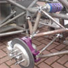
Our thoughts now turned to suspension geometry and how we could make the best use of the 4WD system in that as a car launches the weight transfer lessens frontal grip. With this in mind we decided to engineer a mild rising rate into the rear double wishbone suspension on take off (compression) to restrict weight transfer whilst at the front mild rising rate on take off (droop) to help keep tyre footprint keen at all times. We also paid a huge amount of attention to camber change (or the total lack of it that would be required ). We decided the best way to position the dampers would be cantilever at the rear in order that chassis loading could be supported by the rear diff and torsion box whilst at the front using the same length dampers (although not the same damper in terms of spring rate and damper settings) but fixed in a more conventional upright manner actuated off the top wishbone.
The conventional design of live rear axle (common in most RWD drag cars) and McPherson struts at the front were never considered, because the continuance of the independent Evo rear suspension theme was an important part of our brief whilst at the front the McPherson struts were never considered due to both weight and camber change issues.
With all these considerations now made we were left with an overall track (the track would be ultimately controlled by the virtually unmodified Evo VIII front and rear bodywork), a slightly modified wheelbase, and an engine, gearbox and transfer case package and a third member (rear diff and housing). This allowed us to start on computer generating the front and rear chassis, suspension pick up points and uprights.
The centre of the car (safety cell) was at this stage brought into question, as some of the rules and regulations governing the roll cage design and materials to be used may have limited where the car could race. For this reason we were introduced to the UK arm of the SFI (Safety Foundation Incorporated), the governing body for drag racing. Their instant concern was that depending on the cars ET (elapse time to cover the ¼ mile) as the car developed, and hence got faster we may have had to continually upgrade the safety cell. It was for this reason that with their guidance all parties concerned agreed that the safety cell should meet with 25.1e regulations which would ultimately allow the car to run down to 6.5 second ¼ mile. This spec requires the safety cell to be made from 4130 chrome moly and fully tig welded, however, we decided that for ease of repair the front and rear torsion boxes would be made from CDS3BK and be mig welded.
It was now time to go from a computer generated layout to prototype manufacture. The first task was to perform major surgery to the original ‘drag monster’. This entailed removing as much unnecessary metalwork as possible as ultimately the only use for what was left was to hang front clip (one-piece front end), doors, boot lid and rear spoiler onto. The replacement panels were all to be carbon.
With the remaining shell now at its lightest the creation of the chassis could start. We decided that the engine was to be used as a structural part of the chassis whilst the gearbox was left free to pivot on a chassis mounted spherical rod end. This was done on advice taken from people who already ran high bhp Evo based 4WD drag cars as they had evidence that the gearbox case would indeed twist under load and that making it structural may cause gear selection problems.
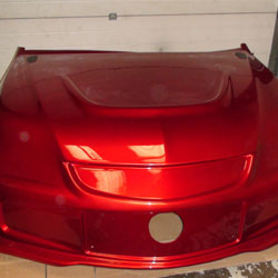
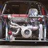
 At this time we were introduced to the inlet manifold and turbo that the car was to use (wow!). The positioning of the turbo was to be as the American based FWD drag cars i.e. centralizing positioned in the bumper. With this position finalized and an exhaust manifold under construction by Primary Designs Limited we could now start on another part of the project, the production of the carbon front clip. This entailed taking an already modified front bumper, aluminum front bonnet and wings and a plastic scuttle panel and creating a smooth drag style plug (the part from which the mould is taken). Whilst creating this plug we decided to slightly widen the front track of the car to both aid stability and create more steering angle. As well as the front clip we also manufactured rear door outer carbon skins, rear boot lid and a rear spoiler to aid parachute deployment. The other panels which were front doors and roof were as supplied and were wet lay-up carbon as opposed to our pre-impregnated carbon.
With the basic chassis well under construction consideration was now made to the overall packaging and balance of the car and we decided that a left hand drive format would make for the best corner weight footprint. This part of the construction involved a lot of the customers time as the safety cage, position of steering wheel, gear lever, carbon paddle shift and pedals (our own floor-mounted carbon set) were all constructed around the customers requirements whilst also meeting with SFI regs.
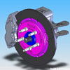
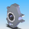
We were now ready to first fix the car (a complete dry build before painting). This again involved lots of Evo400’s time as there were to be a fair amount of out-sourced parts needed i.e. fuel system, propshaft, seat, harness, gauges, wheelie bar, parachute and air jacks etc. Our own alloy radiator and header tank were manufactured and positioned . A major consideration at this stage was the braking system to be used on the car as we were now ready to manufacture the suspension system i.e. wishbones, uprights and steering arms. We were supplied with a carbon fibre braking system which we quickly turned into a computer generated image (CGI) to allow us to fit it onto our CGI of a wheel, tyre, upright and output flange. This would enable us to design and manufacture the brake bells and attach the brake caliper directly to the upright. With the car now rolling round on its wheels fully first fixed but with no bodywork on it, it was shipped off for wiring to DC Electronics.
The next stage, with some of the wiring now completed, was to double check the first fixing to make sure all welding and fabrication was finished on the chassis and the car was shipped off to ATEC for fluid system pipework i.e. hard lines for brake, clutch and fuel system etc.
It was now time to fully strip the chassis and send it and all the bodywork away for painting and various other parts away for powder coating.
With all the parts gathered the pressure was now on to get the car together and try to meet a deadline we had agreed with the customer (James), so that he could start on his test and development program. This would be run by his new business JR Motorsport.
With the car together, the bodywork on, it was time to fire up the engine and give the transmission a whirl. The transmission in the car at this stage consisted of an out sourced 5 speed group N dog box with our paddle shift or semi automatic sequential operating system. Our own front and centre spooled diffs (spooled being a solid piece of engineering, coupling both front wheels together and front and rear drive outputs together to guarantee no transmission slip). Our own up rated cross shafts in both gearbox and transfer case, out sourced front driveshafts, out sourced two piece chrome moly prop shaft, modified 9” spooled third member (we shortened the case and made new output flanges to replace the normal driveshafts that would be found in a third member) and out sourced rear driveshafts. With the car outside (absolutely necessary on a methanol drag car) the engine started effortlessly albeit with a tiny sniff of ‘Easiest’ and ran seamlessly up and down the gears. The noise was amazing !!! (the car was on axle stands, as running this type of car around our industrial estate would not be for the faint hearted)
Computer Generated images of a Spooled Diff |
Third member modifications on CNC lathe |
|
Our aim when taking on this project was a final car weight of as near to1000kgs as possible. This was always going to be difficult as some of the parts in this car were huge in the extreme e.g. the turbo and the third member had a combined weight of over 85kgs, which we hadn’t experienced before, however, this situation was aided by the inclusion of the carbon brakes giving ultra lightweight corners, the titanium tunnels and of course the huge amount of carbon work from front to back, all of which has made for a serious EVOLUTION of the Drag Monster!, and a project which typifies our ‘imagineering’ philosophy. (The finished weight - 1029kgs.)
Coil mount and bracket |
||||

